




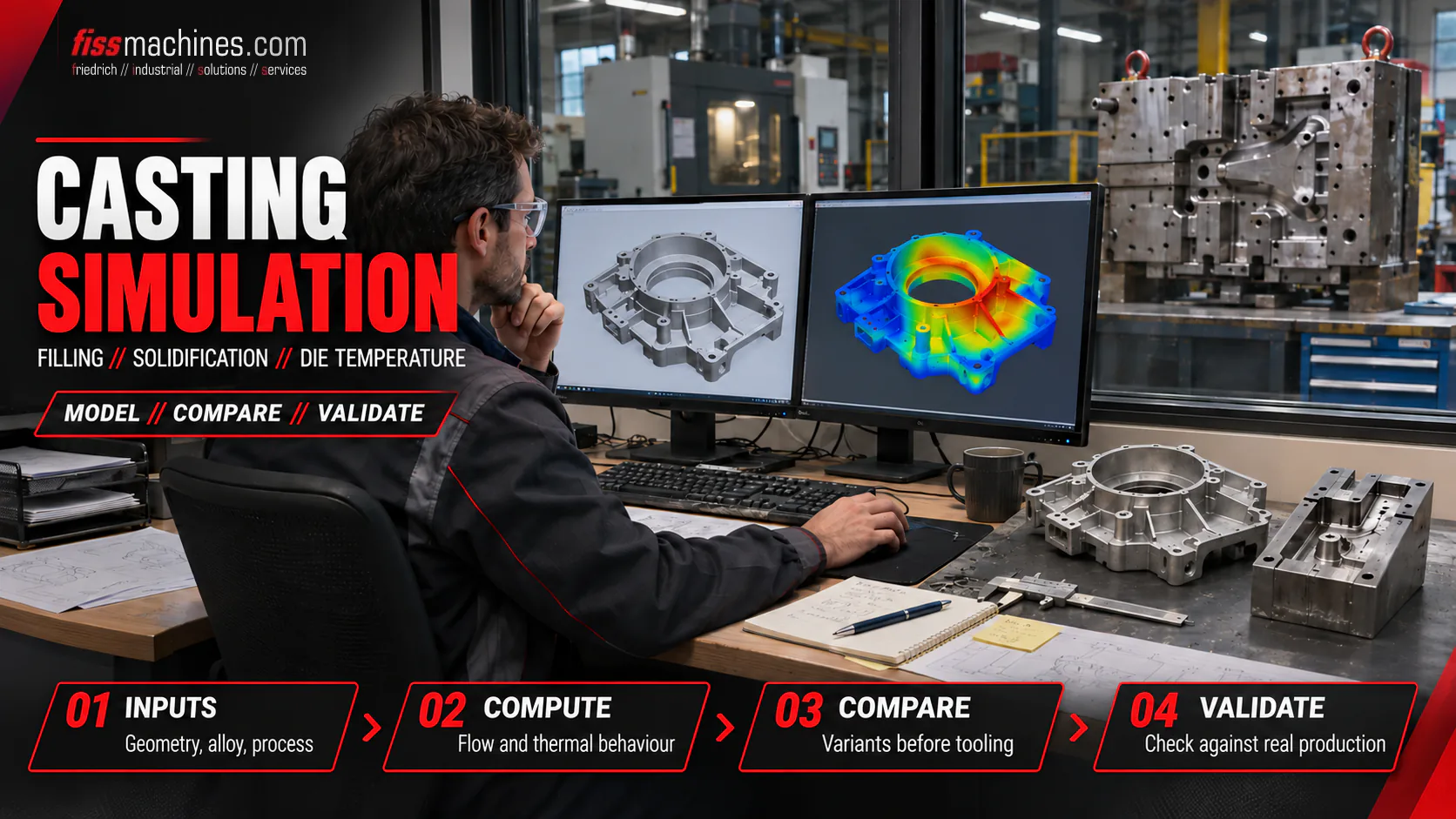
Casting Simulation in Die Casting: What Filling and Solidification Simulation Can Do
A new die casting die is expensive, and every correction after the first trial shots costs time and steel. Casting simulation moves part of this trial and error onto the computer: before the die is machined, engineers can see how the metal flows, where it solidifies last and how the die heats up over many cycles.
What Is Die Casting Simulation?
Die casting simulation is the numerical calculation of mould filling, solidification, heat flow in the die and, optionally, stresses and distortion for a specific casting, gating system and process. It predicts tendencies such as air entrapment, cold flow, shrinkage porosity and hot spots before or during die design.
A simulation does not replace trial shots. It narrows down the options so that the first real shots start from a better design.
What a Die Casting Simulation Computes
The physics of the shot – fill time, gate speed, venting and vacuum – is covered in Mold Filling and Vacuum in Die Casting. A die casting simulation translates this physics into calculation steps that are usually run in sequence.
Filling
Flow of the melt through shot sleeve, runner, gates, cavity and overflows, with velocity, temperature and air distribution over time.
Solidification
Cooling of the casting after filling, solidification sequence, last-to-freeze areas and the effect of intensification pressure.
Die Thermal Cycling
Temperature field of the die over many cycles including spraying, opening times and cooling channels until a steady state is reached.
Stress and Distortion
Residual stresses and distortion of the casting and thermal loads on the die steel, where the software offers a stress module.
The steps depend on each other: a filling result calculated with an unrealistically cold die is of little use, so many projects start with thermal die cycling.
Which Inputs Decide the Quality of a Die Casting Simulation
A die casting simulation is only as good as its input data. These inputs matter most:
- Geometry: casting, runner, gates, overflows, vents and vacuum channels as well as die inserts and cooling channels. Missing overflows or simplified vents distort air entrapment results.
- Alloy data: temperature-dependent properties such as viscosity, density, thermal conductivity, latent heat and solidification range. The material groups are compared in Comparing Die Casting Materials.
- Shot profile: slow and fast shot velocities, switch-over point, intensification and the real plunger movement of the machine.
- Die temperatures and cooling: initial die temperature, temperature control units, cooling channel flow rates and temperatures. The basics are described in Temperature Control in Die Casting.
- Spraying and cycle times: spray duration, blow-off, die open and close times – they control the heat lost per cycle.
- Heat transfer coefficients: the heat flow between casting and die. These values are hard to measure and strongly affect solidification and die temperatures.
Typical Results and How Engineers Read Them
| Result | What It Shows | Typical Consequence in Die Design |
|---|---|---|
| Air and gas entrapment | Where air is enclosed by converging flow fronts | Move or enlarge overflows and vents, change gate position |
| Flow front temperature / cold flow | Where the melt is already too cold when fronts meet | Shorten flow paths, adjust fill time, gate or die temperature |
| Solidification sequence and hot spots | Isolated liquid areas cut off from the gate | Local cooling, jet cooling, squeeze pins, wall thickness changes |
| Porosity tendency | Criteria for shrinkage and gas porosity | Prioritise areas for design changes and X-ray inspection |
| Die temperature field | Hot and cold zones after thermal steady state | Cooling channel layout, spray strategy, soldering risk |
| Distortion and stresses | Deformation after ejection and cooling | Machining allowance, part support, ejection concept |
Porosity and cold flow are shown as tendencies or criteria, not as exact defect sizes. The defect types themselves are explained in Die Casting Defects Explained.
Validating a Die Casting Simulation Against the Real Process
A die casting simulation becomes reliable when it has been compared with the real process. Three sources of evidence are commonly used, followed by calibration:
Shot Curves
Compare the plunger velocity and pressure assumed in the model with the recorded curves of the machine. How to read them is explained in Understanding Shot Curves.
Die Temperatures
Thermocouples in the die or thermal images of the opened die surface show whether the calculated temperature field matches reality. Emissivity and release agent films affect infrared readings.
Real Parts
Short shots, sectioned castings, X-ray or CT images and leak tests show where air, cold flow or porosity actually occur.
Adjust and Document
Correct boundary conditions such as heat transfer or spray cooling, rerun the model and record which values were calibrated.
A calibrated model is a useful starting point for similar parts in the same foundry.
Limits of Casting Simulation
- Input quality: estimated heat transfer coefficients, idealised shot profiles or missing vents lead to plausible-looking but wrong results.
- Model assumptions: mesh resolution, turbulence and air models, and porosity criteria are simplifications. Different software can give different answers for the same part.
- Process scatter: a simulation usually calculates one ideal cycle. Melt quality, die wear, interruptions and machine condition vary in production.
- Interpretation: colour plots need experienced engineers who know which criteria are meaningful for the alloy and part.
Casting Simulation Software for Die Casting
Several providers offer casting simulation software with high pressure die casting functions. The following points are manufacturer statements from their own websites (accessed 6 November 2026), in alphabetical order and without ranking.
FLOW-3D CAST
Process workspaces including HPDC; filling with realistic plunger movement, prediction of cold running, display of entrained air.
ProCAST
HPDC hot and cold chamber, vacuum and other processes; filling, solidification, intensification, porosity and residual stresses; die thermal behaviour.
MAGMASOFT
Shot chamber and cavity filling, tooling heat balance, spraying, die soldering tendency, part distortion and virtual designs of experiments.
NovaFlow&Solid
Casting simulation including HPD and die cycling simulations; release 6.67 (June 2025) names improved mesh handling and squeeze pin behaviour.
Other providers exist. A benchmark with one of your own parts says more than a feature list.
When Die Casting Simulation Pays Off
In die design, simulation accompanies gating concepts, detailed design and validation after the first shots. In troubleshooting, a model of the existing die tests changes before steel is welded or removed. Die layout itself is described in Understanding Die Casting Dies.
- New die for a complex, thin-walled or structural part
- Leak-tight or heat-treatable parts with strict porosity limits
- High die costs or long lead times for die corrections
- Recurring defects whose cause is unclear from shot curves alone
- Transfer of a die to another machine or a different shot profile
- Die modifications for an existing defect would be costly or slow
If several points apply, simulation is usually worthwhile – in-house, through the die maker or an external service. For simple, proven part families with stable scrap rates, it often adds little. Ask for the input data and validation plan, not just colour plots.
Simulation as a Tool, Not a Promise
Die casting simulation shows filling, solidification, die temperatures and distortion before the die is built and helps to locate the causes of defects. Its value depends on realistic inputs, especially shot profile, die temperatures and heat transfer, and on validation with shot curves, thermal data and real parts. Used this way, simulation shortens the path to a stable process – without replacing trial shots.
Questions About Die Casting Simulation
Can Simulation Predict Porosity Exactly?
No. Simulation shows where shrinkage or gas porosity is likely, based on criteria and model assumptions. The actual size and location of pores must be confirmed with X-ray, CT or sectioned parts.
Why Simulate Thermal Die Cycling Before Filling?
The die only reaches its operating temperature after many cycles. Filling and solidification results calculated with a cold or uniform die can therefore be misleading; thermal cycling provides a realistic starting temperature field.
Who Usually Runs the Simulation?
The foundry’s process engineering, the die maker or an external simulation service runs the model, depending on the company. What matters is that the person running it knows the real machine, shot profile and spray practice.
Does Simulation Replace Trial Shots?
No. Simulation reduces the number of design loops and makes trial shots more targeted. Release of a die and process still requires real castings, inspection and documented process parameters.
Talk to FISS About Your Die Casting Process.
FISS supports foundries with machine selection, process optimisation and technical evaluation – and helps match machines to the shot profile your die requires.
Sources
Long, A.; Thornhill, D.; Armstrong, C.; Watson, D.: Determination of the heat transfer coefficient at the metal–die interface for high pressure die cast AlSi9Cu3Fe, Applied Thermal Engineering 31 (2011) 17–18, pp. 3996–4006; abstract via pure.qub.ac.uk, accessed 6 November 2026.
MAGMA Gießereitechnologie GmbH: Die Casting: Optimized Quality, Robust Tooling and Cost Effective Processes, magmasoft.com, accessed 6 November 2026 (manufacturer statements).
Flow Science, Inc.: FLOW-3D CAST, flow3d.com, accessed 6 November 2026 (manufacturer statements).
Keysight Technologies: Casting (ProCAST) Simulation for Die Casting, keysight.com, accessed 6 November 2026 (manufacturer statements).
NovaCast Systems AB: NovaFlow&Solid, novacast.se, accessed 6 November 2026 (manufacturer statements).
FISS Machines: Mold Filling and Vacuum in Die Casting, Understanding Shot Curves and Consulting, fiss-machines.com, accessed 6 November 2026.
